Atomic 4 Owners Manual
ENGINE OPERATION
TO INSURE PROPER OPERATION OF YOU ENGINE AT ALL TIMES, IT IS WELL TO OBSERVE BASIC RULES. THIS IS ESPECIALLY TRUE DURING WINTER MONTHS WHEN THE BOAT IS EITHER IN STORAGE OR USED INFREQUENTLY.
SEE THE INSTRUCTION BOOK FOR PREPARING THE ENGINE FOR WINTER STORAGE. IN ADDITION TO FOGGING THE ENGINE, WE ALSO SUGGEST THAT OIL BE PLACED IN EACH CYLINDER AND THE ENGINE TURNED OVER THREE (3) OR FOUR (4) TIMES TO INSURE ADDED PROTECTION FOR THE VALVES DURING STORAGE.
DURING COLDER WEATHER WHEN BOATS ARE NOT USED REGULARLY, THE ENGINES REQUIRE EXTRA CARE AND ATTENTION. WHENEVER THE ENGINE IS PLACED IN OPERATION, IT SHOULD BE RUN UNTIL THE ENGINE IS THOROUGHLY WARMED UP TO NORMAL OPERATING TEMPERATURE AND THEN IT SHOULD BE OPERATED AT THIS TEMPERATURE FOR 15 TO 30 MINUTES. JUST STARTING AN ENGINE BRIEFLY CHANGES THE TEMPERATURE SLIGHTLY AND INDUCES CONDENSATION TO FORM. THIS CONDITION IS ONE OF THE MAIN CAUSES FOR STICKY VALVES.
IF THE BOAT WILL NOT BE USED FOR A MONTH OR SO, IT IS WELL TO FOG THE ENGINE AND PLACE OIL IN THE CYLINDERS. IT IS NOT ALWAYS POSSIBLE TO CLOSE THE EXHAUST AND THE VALVE MECHANISM IS EXPOSED TO SALT AIR BACKING UP THE EXHAUST PIPE. ALSO, CONDENSATION FORMS INTERNALLY DURING STORAGE. DO NOT JUST START THE ENGINE EACH WEEK OR SO AND RUN IT FOR A FEW MINUTES. SEE PRECEDING PARAGRAPH.
REMEMBER, YOUR BOAT IS IN THE WATER AND SUBJECT TO THE CORROSIVE ACTION OF SALT AIR AND WATER. PROBLEMS THAT MIGHT DEVELOP DUE TO IMPROPER CARE OR OPERATION IN THE FIELD CANNOT BE CONSIDERED AN ENGINE DEFECT AND ARE NOT COVERED BY THE NORMAL ENGINE WARRANTY.
IT IS IMPORTANT TO CHANGE OIL FREQUENTLY AS RECOMMENDED IN THE OWNERS MANUAL. CONTAMINATED OIL DOES NOT PROVIDE ADEQUATE LUBRICATION.
IMPORTANT NOTE:
AT ALL TIMES, REGARDLESS OF FREQUENCY OF OPERATION, IT IS NOT GOOD PRACTICE TO RUN THE ENGINE FOR ONLY A SHORT PERIOD OF TIME. IT SHOULD BE OPERATED 30 MINUTES AT A VERY MINIMUM TO REACH NORMAL OPERATING TEMPERATURE.
IT IS ALSO GOOD PRACTICE TO OCCASIONALLY RUN THE ENGINE AT FULL LOAD FOR A PERIOD OF TIME (A MINIMUM OF 5 MINUTES) TO KEEP THE ENGINE CLEAN OF MOISTURE AND CARBON ACCUMULATIONS FROM SHORT RUN PERIODS OR LONG IDLE PERIODS.
NEVER START THE MOTOR UNTIL THE MOTOR COMPARTMENT HAS BEEN VENTILATED BY EITHER OPENING THE HATCH OR OPERATING THE BLOWER TO REMOVE ANY POSSIBLE FUEL FUMES.
MARINE ENGINE WARRANTY
PRODUCT WARRANTY
SELLER WARRANTS ALL PRODUCTS AND PARTS OF ITS OWN MANUFACTURE AGAINST DEFECTS IN MATERIAL OR WORKMANSHIP FOR A PERIOD OF ONE (1) YEAR FROM DATE OF SHIPMENT WHEN GIVEN NORMAL AND PROPER USAGE AS DETERMINED BY SELLER UPON EXAMINATION, AND WHEN OWNED BY THE ORIGINAL PURCHASER. COMPONENTS PURCHASED BY SELLER AS COMPLETE UNITS AND USED AS AN INTEGRAL PART OF SELLERS EQUIPMENT WILL BE COVERED BY THE STANDARD WARRANTY OF THE MANUFACTURE THEREOF. SELLER WILL REPAIR OR REPLACE F.O.B. ORIGINAL SHIPPING POINT (BUT NOT INSTALL) ANY PART OR PARTS OF ITS MANUFACTURE WHICH IN ITS JUDGMENT, SHALL DISCLOSE DEFECTS IN EITHER MATERIAL OR WORKMANSHIP. IF REQUESTED BY SELLER, PARTS FOR WHICH A WARRANTY CLAIM IS MADE ARE TO BE RETURNED TRANSPORTATION PREPAID TO OUR FACTORY. THIS WARRANTY BECOMES VOID IF ARTICLE CLAIMED TO BE DEFECTIVE HAS BEEN REPAIRED OR ALTERED IN ANY WAY OR WHEN THE ARTICLE HAS BEEN SUBJECT TO MISUSE, NEGLIGENCE OR ACCIDENT OR WHEN INSTRUCTIONS FOR INSTALLING OR OPERATING HAS BEEN DISREGARDED. WE MAKE NO OTHER WARRANTY, EXPRESS OR IMPLIED, AND MAKE NO WARRANTY OF MERCHANTABILITY OF OF FITNESS FOR ANY PARTICULAR PURPOSE, AND THERE ARE NO WARRANTIES WHICH EXTEND BEYOND THE DESCRIPTION OF THE FACE HEREOF. NO EMPLOYEE OR REPRESENTATIVE IS AUTHORIZED TO CHANGE THIS WARRANTY IN ANY WAY OR GRANT ANY OTHER WARRANTY. THE REMEDIES HEREINABOVE AFFORDED TO THE PURCHASER ARE EXCLUSIVE OF ALL OTHER REMEDIES PROVIDED BY LAW. SELLER SHALL NOT BE LIABLE FOR INDIRECT OR CONSEQUENTIAL DAMAGES WHERE THE LOSS SUSTAINED IS OF A COMMERCIAL NATURE.
PRODUCT IMPROVEMENTS
THE MANUFACTURER RESERVES THE RIGHT TO MAKE PRODUCT IMPROVEMENTS AT ANY TIME WITHOUT TAKING RESPONSIBILITY OR OBLIGATION TO MAKE SIMILAR CHANGES OR ADD SIMILAR IMPROVEMENTS ON ANY ENGINES DELIVERED PRIOR TO THOSE CHANGES.
WARRANTY REGISTRATION
ENCLOSED WITH EACH ENGINE IS A WARRANTY REGISTRATION CARD. THIS CARD MUST CONTAIN THE OWNER=S NAME, ADDRESS, SERIAL NUMBER OF THE ENGINE, V-DRIVE AND REVERSE GEARS AND RETURNED TO MEDALIST BEFORE THE WARRANTY BECOMES EFFECTIVE. THIS WARRANTY REGISTRATION MUST TAKE PLACE WITHIN 24 HOURS AFTER RECEIPT OF THE ENGINE.
WARRANTY EXCLUSIONS
THE FOLLOWING SERVICES AND EQUIPMENTS WILL NOT BE REIMBURSED UNDER THE WARRANTY:
1. REPAIRS DUE TO NEGLECT, MISUSE, IMPROPER APPLICATION, ACCIDENT, RACING AND INSTALLATIONS THAT DO NOT MEET MINIMUM STANDARDS AS SET FORTH IN THE INSTRUCTION MANUAL.
2. TUNEUP OR ADJUSTMENT EXPENSES NEEDED FOR CLEANING OF FUEL SYSTEM COMPONENTS DUE TO CONTAMINATION.
3. DAMAGE OR LOSS TO PERSONAL PROPERTY, LOSS OF REVENUE, TOWING CHARGES, STORAGE FEES, FUEL AND TELEPHONE CALLS.
4. DAMAGES OR LOSSES RELATED TO HANDLING AND SHIPPING.
5. EXPENSES RELATED TO REPLACEMENT OF LUBRICANTS, ANTI-FREEZE OR SPECIAL ADDITIVES.
6. FAILURE DUE TO NOT FOLLOWING RECOMMENDED MAINTENANCE SCHEDULES.
7. ALL TRANSPORTATION CHARGES WILL BE THE OBLIGATION OF THE OWNER, SUCH AS FREIGHT, TRAVEL TIME, AND TOLLS.
8. WARRANTY ITEMS RETURNED TO THE FACTORY COLLECT WILL BE BILLED TO THE SHIPPER.
WARRANTY AUTHORIZATION
PRIOR AUTHORIZATION IS REQUIRED FROM THE FACTORY WHERE COMPLETE REPLACEMENT OR OVERHAULING OF THE FOLLOWING IS NECESSARY:
1. COMPLETE ENGINE ASSEMBLY.
2. CYLINDER HEADS OR ENGINE BLOCK.
3. MARINE REVERSE GEAR OR V-DRIVE.
| Models | UJ, UJS, UJR, UJSR, UJVD | |
| Type | Vertical, 4 cycle, L-head | |
| Number of Cylinders | 4 | |
| Bore and Stroke | 2-9/16" x 3-1/8" | |
| Total Piston Displacement in cu. Inches | 64.46 | |
| Spark Plug | Champion J-8 14mm. | |
| Compression Ratio | 6.3 to 1 | |
| Engine Rotation | Counter-Clockwise Viewed from Flywheel End | |
| Reduction Gear Ratio | 2.04 to 1 | |
| V-Drive Reduction Ratios | 1.00 to 1, 1.29 to 1, 1.67 to 1, 2.0 to 1 | |
| Fuel | Standard Gasoline, 92-94 Octane | |
| Maximum Operating Angle | Approx 12 to 15 degrees max. | |
| Length Overall in inches | UJVD - 35-13/16", UJ - 26-3/4", UJR - 31-15/16" | |
| Height above crankshaft center line | 13-1/8" | |
| Maximum Width in Inches | 13-1/8" | |
| Offset - Crank to Prop shaft | 1.042" | |
| Base Depth Below Center line in inches | 6" | |
| Exhaust Flange National Pipe Thread Size | 1-1/4" | |
| Water Inlet National Pipe Thread Size | 3/8" | |
| Water Outlet National Pipe Thread Size | 3/8" | |
| Fuel Pump Connection | 1/8" N.P.T. | |
| Fuel Line - Copper Tubing | 5/16" O.D. | |
| Weight of engine, net pounds | UJ-310, UJR-330, UJVD-335 | |
| Firing Order (No. 1 on Flywheel End) | 1-2-4-3 | |
| Inlet Valve Opens | 5 degrees before TDC | |
| Inlet Valve Closes | 50 degrees after LDC | |
| Exhaust Valve Opens | 45 degrees before LDC | |
| Exhaust Valve Closes | 10 degrees after TDC | |
| Dwell Angle | 31 to 34 degrees |
Brake Horsepower
| RPM | 600 | 1000 | 1500 | 2000 | 2500 | 3000 | 3500 |
| UJS-UJSR | 4 | 7.1 | 11 | 15 | 18 | --- | --- |
| UJ-UJR-UJVD | 5 | 7.3 | 11.9 | 16.2 | 20 | 25 | 30 |
| Carburetor - Zenith 68 Series | 7/8" | |
| Reversing Gear - Paragon | OXKB | |
| Reduction Gear | Paragon | |
| Electrical Equipment UJ-UJR | Standard - 12 volt 35 amp Alternator |
| Piston Skirt Clearance | .0015 Feeler to 5 lbs. Pull | |
| Piston Ring Cap Clearance | .007 to .015 | |
| Connecting Rod End Play | .004 to .008 | |
| Crankshaft End Play - Maintained at front bearing only | .002 to .003 | |
| Valve seat angle | 45 degrees | |
| Oil pump drive end play | .001 to .003 | |
| Distributor point gap clearance | .018 to .020 | |
| Magneto Breaker Point | .014 to .018 | |
| Spark Plug Gap Clearance | 0.035 | |
| Ignition Timing - breaker points just starting to open | TDC | |
| Main Bearing Clearance - on Crankshaft | .001 to .0025 |
| Piston Ring Side Clearance | ||
| Compression Ring (top) | 0.0015 | 0.003 |
| Compression Ring (middle) | 0.001 | 0.0025 |
| Oil Ring | 0.001 | 0.0025 |
| Piston Pin Clearance in Piston | 0.001 | 0.0002 |
| Connecting Rod Clearance (dia) | 0.001 | 0.0025 |
| (# on Rod toward camshaft) | ||
| Valve Tappet Clearance, Intake hot | 0.008 | |
| Valve Tappet Clearance, Intake cold | 0.01 | |
| Valve Tappet Clearance, Exhaust hot | 0.01 | |
| Valve Tappet Clearance - exhaust cold | 0.012 | |
| Valve Seat Width - intake | 1/32" | |
| Valve Seat Width - exhaust | 1/32" | |
| Valve Seat Angle | 45 degrees | |
| Valve Stem Clearance, Intake | 0.0025 | 0.0035 |
| Valve Stem Clearance, Exhaust | 0.0025 | 0.0035 |
| Camshaft Gear Back Lash | 0.002 | 0.004 |
| Idler Gear Back Lash | 0.002 | 0.004 |
| Accessory Gear Back Lash | 0.002 | 0.004 |
| Oil Pump Gear Back Lash | 0.003 | 0.005 |
| Camshaft Bearing Clearance | 0.0015 | 0.0025 |
| Camshaft Bearing Journal | 1.3745 | +.0005 |
| -.0000 |
TORQUE WRENCH TENSION
| Flywheel Stud Nuts | 35 ft. lbs. |
| Cylinder Head Stud Nuts | 35 ft. lbs. |
| Connecting Rod Bolt Nuts | 33 ft. lbs. |
| Main Bearing - Front | 60 ft. lbs. |
| Main Bearing - rear | 60 ft. lbs. |
| Manifold Studs | 35 ft. lbs. |
| Spark Plugs | 30 ft. lbs. |
Note to Atomic Stevedore Owners - All instructions in this book apply equally to Atomic Four and Atomic Stevedore models. Where there is a difference in specifications or adjustments it is so indicated.
GENERAL INSTRUCTIONS
Give your engine every chance to perform properly. If you become familiar with the operating requirements it will give you long dependable service. Check the alignment of the engine to the propeller shaft after the boat is first placed in the water. If you are in doubt how to proceed, write the factory for special service bulletin.
Add the necessary lubricating oil to the engine. The quantity is dependent upon the angle of installation and whether your engine is a direct or reduction drive model. Fill the oil base with 4 to 5 quarts of good grade SAE 30 detergent oil or until the dipstick shows full. The dipstick is located just forward of the water pump on the reverse gear housing. Check the oil level after the engine has been operated for a short time.
Check choke control to make sure choke valve fully closes. Then push choke back to normal position and make sure choke butterfly in carburetor fully opens. Check throttle control to make sure it provides for full movement of the throttle lever from idling position to fully open position.
Reversing gear controls must allow the clutch to lock in forward position and also into reverse position. Restricted or partial engagement will cause undue wear. Reversing gears and reduction gears are lubricated by the engine oiling system. Fuel like must be connected to fuel pump located just forward of reversing gear on carburetor side of the engine. A hand primer is provided to fill the fuel bowl for initial start. Use 5/16" copper tubing for fuel line.
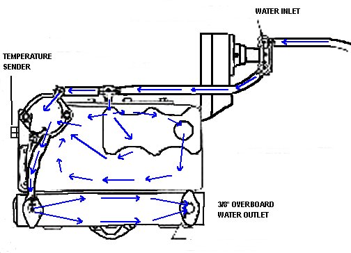
An unrestricted water supply must be provided. Use a �" through hull fitting with scoop forward. Locate scoop where it will have a supply of water at all times regardless of running position or rough seas. Water pump has 3/8" suction and manifold has 3/8" water outlet. Use non-collapsable hose for suction side.
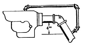
Figure 1.
Exhaust pipe is 1-1/4" iron pipe size. It should be installed without sharp bends and slop downward to its outlet to discharge water. The connection for discharge water should be at least 4" below the bottom of the manifold exhaust flange opening. See Figure 1.Suggestions before starting your new engine:
CAUTION: ENGINE IS SHIPPED LESS OIL. FILL WITH SAE 30 CLASS A DETERGENT OIL BEFORE STARTING.
Ventilate engine compartment by opening hatches and starting blower fans if you have them.
Check fuel supply and make sure fuel lines are tight. Any fuel seepage or leaks should be corrected before you attempt to start engine.
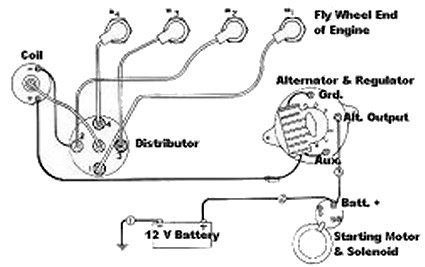
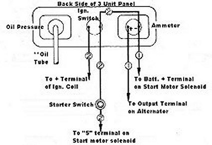
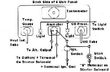
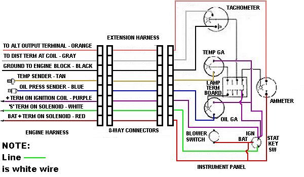
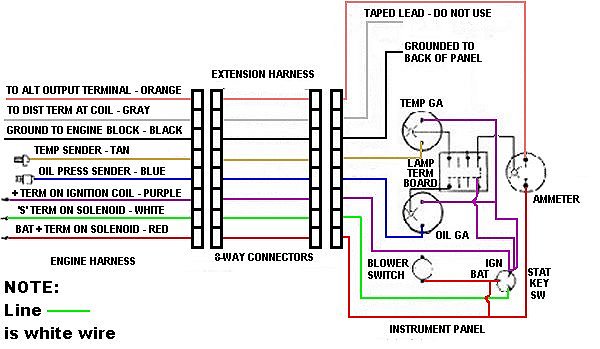
Check all electrical connections. A wiring diagram for your particular model is included in this book. Ground is negative. Ground terminal should be attached to engine block.
Do not allow flames or sparks near battery openings. Gases produced during normal charging are explosive.
Make sure water pump is lubricated with water pump grease.
Starting you new engine:
1. Clutch lever should be in neutral position.
2. Fill fuel pump bowl using the hand primer on the fuel pump.
3. Place throttle lever at � open position.
4. Pull out choke rod.
5. Turn on ignition and start engine.
6. As soon as engine starts, gradually push in choke lever until choke valve is completely open.
7. Run engine at idling speed of 600 to 1000 rpm.
8. Check oil pressure - 45 to 55 pounds when engine is cold. Check oil after about 10 minute of running. Add oil to bring level to full mark if needed.
9. Check cooling system and make sure water pump is operating by checking water out of exhaust pipe. Temperature indicated on gauge should gradually go up to 140-160 degrees.
10. If oil pressure or water flow (or operating temperature) is not normal, stop engine at once and check installation to correct problem.
11. When shifting into forward or reverse position, engine should be running at 600-1000 rpm.
After the break-in period a good cruising speed for sail boat installations is about 2000 RPM or about 80% of the maximum engine speed obtainable.
61 Series - 1967 and before
 |
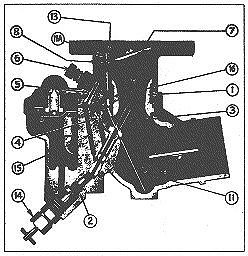 |
2 Main Jet
3 Main Dis. Jet
4 Well Vent
5 Idling Jet
6 Idling Needle Valve
7 Throttle Plate
8 Idle Discharge Plug
9 Throttle Shaft
10 Restriction Bushing
11 & 11A - Pick up tube
12 Throttle stop screw (Not Illustrated)
13 Pick-up Tube metering orifice
14 Main jet adjustment
15 Idle fuel channel
16 Idle air channel
If the adjustments have been altered, start with a standard setting, which is:
1, Throttle stop screw - 1-1/2 turns (to right) from fully closed position of throttle plate (7).
2. Idling needle valve (6) one turn open (to left) from seat.
3. The main jet adjustment (14) 2-1/2 turns open (to left) from seat.
ADJUSTMENTS
If the engine, after running satisfactorily, suddenly ceases to perform properly, look over the intake manifold and the carburetor flange gaskets, throttle, choke and fuel connections. Make sure that throttle and choke valves open and close correctly and that fuel enters the carburetor in a free and steady stream. Do not change carburetor adjustments until other causes of trouble have been investigated.
Changes in adjustment should be necessary only with change in fuel or climate.
Before making any adjustments, warm up the engine thoroughly so that the intake manifold feels warm to the hand.
IDLE AND LOW SPEED ADJUSTMENT
Close the throttle slowly until desired idling speed is reached.
Turn idling needle valve (6) gradually to right and left until the engine runs steady and as fast as this throttle position will permit.
Turning the idling needle valve to right (in) makes the mixture richer, to left (out) makes the mixture leaner.
If a satisfactory adjustment cannot be obtained, examine the idling jet (5) and the idle discharge plug (8) to make sure that dirt or water does not obstruct the free flow of the moisture through these parts.
After completing the adjustments set throttle stop screw (12) for desired idling speed.
INTERMEDIATE AND HIGH SPEED ADJUSTMENT
The mixture at intermediate and high speed is controlled by the main jet (2), and the wall vent (4).
The main jet may be either of fixed size or adjustable. Whether fixed or adjustable, remove main jet (2) and blow out with compressed air or rinse in clean gasoline to remove water or dirt which may obstruct the metering orifice.
If adjustable, adjustment should be made as follows: (i) Open throttle about one-third; (ii) loosen packing nut on main jet adjustment (14); (iii) turn main jet adjustment to right (in) until the engine speed is noticeably reduced; (iv) turn main jet adjustment slowly to left (out) until the engine runs smoothly and as fast as this throttle position will permit; (v) hold needle valve in position and tighten packing nut after completing the adjustment.
Compensation is controlled by the well vent (4). A richer mixture, at high speeds is obtained with a smaller well vent and a leaner mixture with a larger well vent. If the mixture suddenly becomes too rich at high speeds, examine the well vent and make sure that it is not obstructed. Inspect these jets for water and dirt.
STARTING
Open the throttle about one-quarter. Pull the choke control out all the way. Step on the starter. As soon as the engine starts, push the choke control in about one-third of the way and as the engine warms up, continue to push it in gradually until the choke valve is wide open.
FUEL LEVEL
Correct setting of the float which controls the fuel level is of utmost importance. The fuel level is set at the factory for regular motor gasoline and a pump pressure of 2-lbs.per square inch.
ZENITH 68 SERIES CARBURETOR
OPERATION AND SERVICE
The Zenith 68 series carburetors are of updraft single venturi design. They are made in 7/8" and 1" S.A.E. barrel sizes; with 7/8" and 1" S.A.E. flange sizes. They are made with selective fuel inlet, and with or without a main jet adjustment.
These carburetors are "balanced" and "sealed", and the semi-concentric fuel bowl allows operation to quite extreme angles without flooding or starving. This design makes them particularly adaptable to smaller form tractors and a great variety of agricultural machines and industrial units.
FUEL SUPPLY SYSTEM
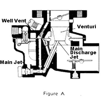
The fuel supply system is made up of the threaded fuel inlet, the fuel valve seat, fuel valve need, float and fuel boat, as illustrated in Figure A.
The fuel supply line is connected to the threaded inlet. The fuel travels through the fuel valve seat and passes around the fuel valve and into the fuel bowl. The level of the fuel in the fuel chamber is regulated by the float through its control of the fuel valve. The fuel valve does not open and close alternately but assumes an opening, regulated by the float, sufficient to maintain a proper level in the fuel chamber equal to the demand of the engine according to its speed and load.
The inside bowl vent as illustrated by the passage originating in the air intake and continuing through to the fuel bowl, is a method of venting the fuel bowl to maintain proper air fuel mixtures even though the air cleaner may become restricted. This balancing is frequently referred to as an "inside bowl vent."
IDLE SYSTEM
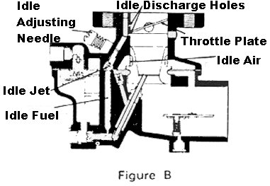
The idle system as shown in Figure B, consists of two idle discharge holes, idle air passage, idle adjusting needle, idle jet, and fuel pick-up passage.
The fuel for idle is supplied through the main jet to a well directly below the main discharge jet. The pick-up passage is connected to this well by a restricted drilling at the bottom of this passage. The fuel travels through this channel to the idle jet calibration. The air for the idle mixture originates back of (or from behind) the main venturi. The position of the idle adjusting needle in this passage controls the suction on the idle jet and thereby the idle mixture. Turning the needle in closer to its seat results in a greater suction with a smaller amount of air and therefore a richer mixture. Turning the needle out away from its seat increases the amount of air and reduces the suction, and a leaner mixture is delivered. The fuel is atomized and mixed with the air in the passage leading to the discharge holes and enters the air stream at this point.
HIGH SPEED SYSTEM
The high speed system, Figure C., controls the fuel mixture at part throttle speeds and at wide open throttle. This system consists of a venturi, controlling the maximum volume of air admitted into the engine; the main jet, which regulates the flow of fuel from the float chamber to the main discharge jet; the well vent, which maintains uniform mixture ratio under changing suction and engine speeds; and a main discharge jet, which delivers the fuel into the air stream.
The main jet controls the fuel delivery during the part throttle range from one-quarter to full throttle opening. To maintain a proper mixture ration a small amount of air is admitted through the well vent into the discharge jet through the air bleed holes in the discharge jet at a point
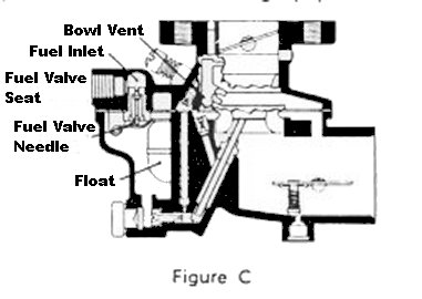
At high speeds the fuel flows from the fuel chamber through the main jet and into the main discharge jet where it is mixed with air admitted by the well vent, and the air-fuel mixture is then discharged into the air stream of the carburetor.
CHOKE SYSTEM
The choke, consists of a valve mounted on a shaft located in the air entrance and operated externally by a lever mounted on the shaft. The choke valve is used to restrict the air entering the carburetor. This increases the suction on the jets when starting the engine. The choke valve is of a "semi-automatic" type, having a poppet valve incorporated in its design, which is controlled by a spring.
The poppet valve opens automatically when the engine starts and admits air to avoid over-choking or flooding of the engine. The mixture required for starting is considerably richer than that needed to develop power at normal temperatures. As the engine fires and speed and suction are increased, the mixture ratio must be rapidly reduced. This change is accomplished through adjustment of the choke valve and the automatic opening of the poppet valve to admit more air when the engine fires.
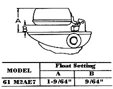
FLOAT SYSTEM
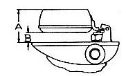
The "A" dimension should be 1-5/32" plus or minus 3/64".
Float Level. Check position or float assembly for correct measurement to obtain proper float level using depth gauge. NOTE: Do not bend, twist or apply pressure on the float bodies.
With bowl cover assembly in an inverted position, viewed from free end of float, the float bodies must be centered and at right angles to the machined surface. The float setting is measured from the machine surface (no gasket) of cover to top side of flat bodies at highest point.
Bending Float Lever. To increase or decrease distance between float body and machined surface use long nosed pliers and bend lever close to float body. NOTE: Replace with new float if position is off more than 1/16".
ELECTRICAL SYSTEMS
WATER COOLING SYSTEMS
The two drain plugs and a pipe cap removed at the factory are in a small bag attached to the barburetor lever. Replace one plug in the bottom of water pum and one in the rear of the manifold near the exhaust flange. Replace the pipe cap on the drain nipple out of the cylinder block water jacket located immediately alongside the distributor.
WATER TEMPERATURE
An automatic by-pass temperature control is standard equipment on the engine. This temperature control valve is required to maintain proper engine operating temperatures. If an engine is operated too cold, condensation may form in the valve chamber causing sticky valves and other malfunctions.
PREPARING ENGINE FOR SPRING SERVICE
Preparation of the engine should include all these items of overhaul necessary to permit satisfactory operation of the engine. Many engines properly serviced in the spring will give a full season of carefree pleasure. The amount of effort to be expended will be determined somewhat by the storage of lay-up procedure of the previous fall. Refer to preparations for starting the engine for the first time.
1. Tighten all nuts and bolts to proper torque. Replace all drain plugs and caps.
2. Manifold - Replace drain plug. Check manifold bolts for tightness since some gaskets shrink more than others.
3. Water Pump - Close drain cock and replace drain plug. Lubricate pump by grease cups. Replace packing if required. DO NOT OPERATE PUMP WITHOUT WATER.
4. Lubrication System - Remove all oil from oil pan and reverse gear housing. Refill with quantity specified in "Lubrication Group".
5. Cylinders - Remove spark plugs. Pour one or two ounces of oil in cylinders to lubricate walls, rings, etc., turn engine over without spark plugs in place.
6. Valves and tappets - Check and lubricate if required. Remove seal over breather tube end.
7. Distributor - Clean and lubricate as required. Remove any moisture seals. Clean and set distributor points.
8. Spark plugs - clean spark plugs and re-set gap to .035". Replace burned or broken plugs.
9. Ignition wires - Replace damaged or brittle ignition wires. High tension electrical leakage prevents good operation of engine.
10. Starting Motor - See that the starter pinion is clean and lubricated with light oil. Remove any moisture seals. Lubricate bearings. Clean commutator and brushes with sandpaper. Do not use emery cloth.
11. Alternator - Does not require any special care or lubrication.
12. Battery - Reinstall fully charged batter. Clean the cable terminals and fasten securely to clean battery terminals. Coat terminals with vaseline or grease to reduce corrosion, and then attach battery cables.
13. Fuel system - See that fuel system is clean and free from scale, sludge, or obstructions. Drain out any water that has accumulated in tanks or fuel lines. Check over for loose connections, tightening any found. Remove cover from carburetor air intake. Oil carburetor choke and throttle carburetor air intake. Oil carburetor choke and throttle shafts. Check for easy operation. Clean flame arrestor.
14. Exhaust system - remove moisture seal.
15. Turn engine over by hand with the spark plugs out to see that all bearings are free.
16. With boat in water, check freedom of propeller shaft in bearings and alignment of propeller shaft with engine.
17. Tighten stuffing box just enough to stop leakage along shaft. Excessive tightening will cause power loss and burned stuffing material.
18. Clean motor thoroughly and repaint.
PREPARING ENGINES FOR WINTER STORAGE
Neglect in preparing an engine for winter storage may lead to annoying or costly damage which will not be seen until the engine is prepared for use the following spring. The engine should be carefully covered to give complete protection from rain and snow. Drain completely to avoid damage from freezing.
1. Fog the engine. Run the engine at about 800 RPM and using about 4 ounces of oil slowly pour it into the carburetor to coat the combustion chamber and cylinder walls. Stall the engine by pouring the last two ounces in rapidly. Also add about two tablespoons of oil in each cylinder through spark plug hole.
2. Lubrication system - The oil pan and lubrication system should be drained of old or contaminated oil so that any moisture or acid present in the oil will not cause corrosion damage during winter. Two or three quarts of new clean oil should be pumped through the system by turning the motor by hand or electric starter. This should distribute a film of clean oil to act as a rust preventive. Regular rust preventive oils can be obtained.
3. Cylinder blocks - A pipe cap is found on the distributor side of the engine. Remove and leave off.
4. Manifold - A pipe plug will be found in the right side and to the rear end of the exhaust manifold. Remove and leave out.
5. Water Pump - Pumps are particularly susceptible to damage from freezing because of the restricted space and clearances. The pump should be carefully drained by loosening the cover. The pump should be dry during the winter.
6. Electrical system - Remove the battery and store it at the boat yard or at your local battery dealer. Loosen the distributor cap for ventilation and protect all other electrical parts for moisture.
7. Fuel System - All gasoline should be drained from carburetor, fuel pump, feed lines, filters, and tanks. This is to prevent development of sludge or gum in the system. The carburetor air intake should be covered by water-proof paper or cloth and sealed to prevent entrance of moisture into engine by way of the intake valves that are open.
8. Exhaust system - Exhaust pipes should be drained free of water. Allow the exhaust pipes to dry out. Seal exhaust pipe end to prevent entrance of moisture into the engine through exhaust valves that are open.
9. Rust prevention - exposed metal parts liable to rust should be coated with grease or rust preventive compound.
WHAT TO DO WHEN YOUR MOTOR DOES NOT OPERATE PROPERLY
The following suggestions will be of assistance in locating and remedying motor troubles. They are also mentioned to assist the operator in making emergency repairs. However, when serious trouble occurs, a competent service man should be called.
The operation of a motor depends primarily on three factors: an unfailing fuel supply; uninterrupted ignition, and good compression. Failure of either the first two will prevent starting or cause loss of power. It may also cause difficult starting or sudden stopping.
If a motor, which has previously been operating satisfactorily, refuses to start or stops with but slight warning and without the noise of a breaking part - it is reasonable to assume that either the fuel supply has been cut off or the ignition has failed. The first step should therefore be to determine which of the two systems is at fault.
FIRST: See that there is gasoline in the tank. Use regular gasoline.
SECOND: It is possible to have plenty of fuel and still be unable to fill the carburetor. This may be caused by too small a vent hole in the gasoline tank cap. The gasoline pipe may be air bound. Test the carburetor by uncoupling the pipe at the carburetor connection. If the fuel does not flow freely, the fuel line may be plugged. Blow or run a wire through the pipe to clean it. The strainer in the fuel pump or in the carburetor may also be plugged.
THIRD: Flooding a carburetor by over-using the choke may cause the misture to become too rich. In this instance, remove the spark plugs and turn the engine over several revolutions.
FOURTH: Look for water in the fuel. If water is found, clean the fuel tank, fuel pump, fuel line and carburetor.
FIFTH: Check for an air leak in the intake manifold. This can be easily tested by squirting oil around the intake connections.
If the fuel system is O.K. check as follows for ignition troubles.
FIRST: Be sure the ignition switch is turned to the "ON" position.
SECOND: Look for a fouled or broken spark plug.
THIRD: Check for weak spark. If a bright spark jumps across the gap between the two points of the plug when the engine is turned over, the ignition system is undoubtedly in working order. This may be verified by making the same test with each wire. The gap between the spark plug points should be approximately .035" (or the thickness of a thin dime).
FOURTH: Check for a broken electrical circuit.
FIFTH: The cause may be due to a ground. Poor installation will cause a ground. Be sure all electrical wires are clean and well insulated.
SIXTH: Poor contact at distributor breaker points.
SEVENTH: Distributor may be out of time.
TROUBLE SHOOTING
A gasoline engine depends upon three main factors for proper operation; an unfailing fuel supply, uninterrupted ignition, and good compression. When any one of these are not present, or present only intermittently, engine failure will result. The following "trouble shooting" information is designed to help the operator locate and overcome some of the most probable causes of engine failure, or improper operation. "Probable Causes" are listed in the most likely order of occurrence. Only one correction should be attempted at a time and that possibility eliminated before going on to the next.
TROUBLE SHOOTING PROCEDURES
| TROUBLE | PROBABLE CAUSE | CORRECTION |
| Starter will not crank engine | Discharged Battery | Charge or replace battery |
| Corroded battery terminals | Clean terminals | |
| Loose connection in starting circuit | check and tighten all connections | |
| Defective starting switch | Replace switch | |
| Starter motor brushed dirty | Clean or replace brushes | |
| Jammed Bendix gear | Loosen starter motor to free gear | |
| Defective Starter Motor | Replace motor | |
| Starter motor turns but does not crank engine | Partially discharged battery | Charge or replace battery |
| Defective wiring or wiring of too low capacity | Check wiring for worn acid spots. | |
| Broken Bendix Drive | Remove starter motor and repair drive | |
| Engine will not start | Empty fuel tank | fill tank with proper fuel |
| Flooded Engine | Remove spark plugs and crank engine several times. Replace plugs. | |
| Water in fuel system | If water is found, clean tank, fuel lines, and carburetor. Refill with proper fuel. | |
| Inoperative or sticking choke valve | Check valve, linkage, and choke rod or cable for proper operation. | |
| Improperly adjusted carburetor | Adjust carburetor | |
| Clogged fuel lines or defective fuel pump | Disconnect fuel line at carburetor. If fuel does not flow freely when engine is cranked clean fuel line and sediment bowl. If fuel still does not flow freely after cleaning, repair or replace pump. | |
| Engine will not start. (Poor compression and other causes) | Air leak around intake manifold | Check for leak by squirting oil around intake connections. If leak is found, tighten manifold and if necessary replace gaskets. |
| Loose Spark Plugs | Check all plugs for proper seating, gasket and tightness. Replace all damaged plugs and gaskets. | |
| Loosely seating valves | Check for broken or weak valve springs, warped stems, carbon and gum deposits, and insufficient tappet clearance | |
| Damaged cylinder head gasket | Check for leaks around gasket when engine is cranked. If a leak is found replace gasket. | |
| Worn or broken piston rings | Replace broken and worn rings. Check cylinders for "out of round" and "taper". | |
| Excessive engine temperature | No water circulation | Check for clogged water lines and restricted inlets and outlets. Check for broken or stuck thermostat. Look for worn or damaged water pump or water pump drive. |
| Engine temperature too low | Broken or stuck thermostat | Replace thermostat. |
| Engine will not start. (Ignition System) | Ignition switch "off" or defective | Turn on switch or replace |
| Fouled or broken spark plugs | Remove plugs and inspect for cracked porcelain, dirty points, or improper gap. | |
| Improperly set, worn or pitted distributor points. Defective ignition coil. | Remove center wire from distributor cap and hold within 3/8 inch of motor block. Crank engine. Clean sharp spark should jump between wire and block when points open. Clean and adjust points. If spark is weak or yellow after adjustment at points, replace condenser. If spark still is weak or not present replace ignition coil. | |
| Wet, cracked, or broken distributor | Wipe inside surfaces of distributor. Dry with clean cloth. Inspect for cracked or broken parts. Replace parts where necessary. | |
| Improperly set, worn, or pitted magneto breaker points. (Magneto models only) | Remove spark plug wire and hold within 3/8 inch of engine block. Clean, sharp spark should jump between wire and block when engine is cranked. If spark is weak or not present clean and adjust breaker points. | |
| Engine will not start. (Poor compression and other causes) | Improperly set, worn, or pitted timer points. Defective coil or defective condenser. | Remove spark plug wire and hold within 1/8" inch of engine block. A clean sharp spark should hump between wire and block when engine is cranked. Clean and set timer points. If spark still is not present when engine is cranked, replace coil. |
| Improper timing | Set timing. | |
| No Oil Pressure | Defective gauge or tube. | Replace gauge or tube. |
| No oil in engine | Refill with proper grade oil. | |
| Dirt in pressure relief valve | Clean valve | |
| Defective oil pump, leak in oil lines or broken oil pump, oil lines or broken oil pump drive. | Check oil pump and oil pump drive for worn or broken connections. | |
| Loss of RPM (Boat or associated equipment) | Damaged propeller | Repair propeller |
| Bent rudder | Repair | |
| Misalignment | Realign engine to shaft | |
| Too tight stuffing box packing gland | Adjust | |
| Dirty boat bottom | ||
| Vibration | Mis-firing or pre-ignition | See correction under mis-firing and pre-ignition. |
| Loose foundation or foundation bolts | ||
| Propeller shaft out of line or bent | ||
| Propeller bent or pitch out of true | ||
| Pre-Ignition | Defective spark plugs | Check all spark plugs for broken porcelain, burned electrodes or electrodes out of adjustment. Replace all defective plugs or clean and reset |
| Improper timing | See instructions for retiming | |
| Engine carbons | Remove cylinder head and clean out carbon | |
| Engine overheating | See correction under "Engine Temp." portion of this table. | |
| Back-Firing | Insufficient fuel reaching engine due to dirty lines, strainer or blacked fuel tank vent. Water in fuel. | See correction under "Engine will not start" portion of this table. |
| Poorly adjusted distributor. | See correction under "Engine will not start" portion of this table. | |
| Low Oil Pressure | Too light body oil | Replace with proper weight oil. |
| Oil leak in pressure line | Inspect all oil lines. Tighten all connections. | |
| Weak or broken pressure relief valve spring. | Replace spring | |
| Worn oil pump | Replace pump | |
| Worn or loose bearings | Replace bearings | |
| Oil Pressure too high | Too heavy body oil | Drain oil and replace with oil of proper weight |
| Stuck pressure relief valve | Clean or replace valve | |
| Dirt or obstruction in lines | Drain and clean oil system. Check for bent or flattened oil lines and replace where necessary. | |
| Sludge in oil | Infrequent oil changes | Drain and refill with proper weight oil |
| Water in oil | Drain and refill. If trouble persists, check for cracked block, defective head gasket and cracked head. | |
| Dirty oil filter | Replace filer (if one is mounted on engine) |
A FINAL WORD
Universal's interest in both customer and product continues long after the engine is installed. Within the limits of our specifications, the company's service department is ready to serve your maintenance and repair needs quickly. In addition, all Universal factory personnel will promptly answer inquiries regarding maintenance, installation or special adaptions.
If you will use judgment and care in operating your Universal engine, use sufficient quantities of the recommended lubricants, stay on the alert for the first signs of trouble, and contact Universal whenever you need aid, the life and usefulness of your Universal power package will be greatly increased.
NOTICE: Some pages have affiliate links to Amazon. As an Amazon Associate, I earn from qualifying purchases. Please read website Cookie, Privacy, and Disclamers by clicking HERE. To contact me click HERE. For my YouTube page click HERE